Marine chocks

ISO13729 Type B Bulwark Mounted Closed Chock

Material: ZG230-450 Steel

Standard: ISO13729

Type: Bulwark-Mounted

Surface: Zinc rich primer

Certifications.: CCS, ABS, BV, DNV, LR, etc.

Introduction:

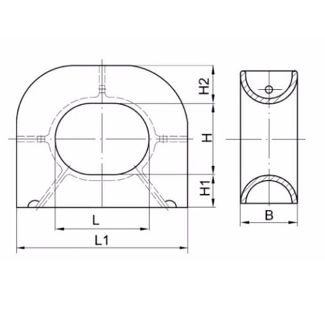
The closed chock is a common ship device installed on the ship to guide the movement of the ropes. In the ISO 13729-2012 standard, there are two types of closed chocks: A type and B type. Type A is installed on the deck and type B is installed on the bulwark.

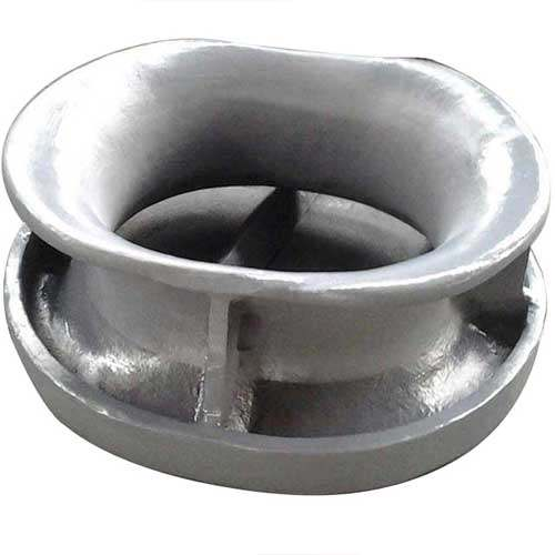
The marine chock is an important mooring equipment. There’re different types of mooring chocks with different standards including ISO, JIS, DIN, NS. SWL will be from 8KN to 3000KN according to your requirements. In the process of mooring ship, it bears huge loads. Usually, the ship bollards and mooring chock are for the whole ship mooring use. The general bow and stern of ship block the bollard fairlead, quantity large. Of intermediate section above without or bollards, fairlead rarely. Fairlead is oblique chock more insurance, because it is closed, the cable will not jump out. The triangle chocks are widely used for small boats and different vessels, such as container vessels, tankers, bulk carriers, tug, dry cargo vessels, etc.

Marine mooring chock has two types: deck mounted chock & bulwark mounted chock. The material is casting steel ZG230-450 normally. IACS approved quality to withstand all conditions. Certificated by BV, ABS, LRS, DNVGL, RS, IRS, CCS, KR, NK, etc. We could also provide you with a customized design with CAD drawings.

Machine Specifications

Parameters of ISO13729 Type B Bulwark Mounted Closed Chock:
Form 1:
Nominal  l1 l2 H1 H2 R R1 R2 R3 R4 R5
size
L*H*D
 250×200×214  516 441 466  306 100 233 153 108 96 150
 300×250×286 638 554 588 410 125 294 205 144 128 180
 350×250×333 736 646 636 449 125 318 224.5 168 150 200
 400×250×381 834 736 684 450 125 342 225 192 172 250
 450×250×381 884 786 684 450 125 342 225 192 172 250
 500×250×381 934 836 684 450 125 342 225 192 172 250
 400×250×428 882 778 732 515 125 366 257.5 216 194 250
 450×250×428 932 828 732 515 125 366 257.5 216 194 250
500×250×428 982 878 732 515 125 366 257.5 216 194 250
500×400×428 982 878 882 665 200 441 332.5 216 194 250
500×250×525A 1078 976 828 551 125 414 275.5 264 240 320
500×400×525A 1078 978 978 701 200 489 350.6 264 240 320
500×250×525B 1078 976 828 554 125 414 277 264 238 320
500×400×525B 1078 978 978 704 200 489 352 264 238 320
Form 2:
Nominal R6 d1 d2 T  θ Welding SWL Wire  Calculated
size leg Rope Weight
L*H*D length Diameter -
- z1 z2 KN t (recommended) (kg)
 250×200×214 138 108 80 12 44° 6 5 226 23 18 49
 300×250×286 164 144 100 16 44° 8 6.5 422 43 24  100
 350×250×333 182 168 120 18 55° 9 7 549 56 28 141
 400×250×381 230 192 120 20 47° 10 8 687 70 32 184
 450×250×381 230 192 120 20 47° 10 8 706 72 32 194
 500×250×381 230 192 120 20 47° 10 8 765 78 32 202
 400×250×428 228 216 120 22 56° 10 9 883 90 36 264
 450×250×428 228 216 120 22 56° 10 9 912 93 36 276
500×250×428 228 216 120 22 56° 10 9 932 95 36 288
500×400×428 228 216 120 22 56° 10 9 893 91 36 311
500×250×525A 296 264 120 24 53° 10 9.5 1148 117 44 379
500×400×525A 296 264 120 24 53° 10 9.5 1158 118 44 408
500×250×525B 294 264 120 26 53° 10 10.5 1413 144 44 405
500×400×525B 294 264 120 26 53° 10 10.5 1383 141 44 442

Inquiry Now


    Related Products